PLC (What is PLC?)
PLC, an acronym for 'Programmable Logic Controller', is a specialized computer designed for reliable operation in harsh industrial environments, such as extreme temperatures, humidity, dryness, or dusty conditions.
PLCs are utilized for automating industrial processes such as manufacturing assembly lines, ore processing plants, or wastewater treatment facilities. PLCs share many features of personal computers that you have at home.
Both have a power supply, CPU (Central Processing Unit), inputs and outputs (I/O), memory, and an operating software (although this is a different kind of operating software).
The main differences are that a PLC can perform discrete and continuous functions that a personal computer cannot achieve.
Moreover, a PLC is much better suited for industrial environments. A PLC can be considered as a 'rugged' digital computer that manages the electromechanical processes of an industrial environment.
PLCs play a vital role in automation by forming part of a larger SCADA system.
A PLC can be programmed according to the operational requirements of the process. In the manufacturing industry, due to the changing nature of production, there will be a need for reprogramming. To overcome this challenge, PLC-based control systems were introduced.
Before we look at the various applications of PLCs, we will first discuss the fundamentals of PLCs. If you want to learn how to program PLCs, you should consider checking out some different online PLC training courses.
These courses can assist you in starting your journey in control engineering.
PLC Fundamentals
PLCs were invented by Dick Morley in 1964. Since then, they have revolutionized the industrial and manufacturing sectors. There is a wide range of PLC functions such as timing, counting, calculations, comparisons, and processing various analog signals.
The main advantage of PLCs over a 'hardwired' control system is that you can go back and change it after programming the PLC at a low cost (just the cost of the programmer's time).
In a hardwired control system, you essentially have to disconnect the wires and start over (which is more expensive and takes longer).
To better understand this advantage, let's look at an example.
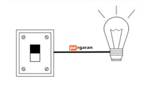
Imagine a light connected to a switch. Generally, the light operates in two states: on and off. Now you are tasked with making the light turn on only after 30 seconds when the switch is turned on.
With this hardwired setup, we face a challenge. The only way to achieve this goal is to completely rewire the circuit to add a timing relay. This is a hassle for a minor change.
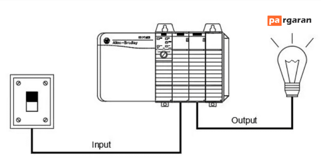
This is where a programmable logic controller comes into the picture, as it allows for changes without the need for additional wiring and hardware.
Rather, it requires a simple change in code. Programming the PLC to turn on the light only 30 seconds after the switch is turned on. Thus, using a PLC, multiple inputs and outputs can easily be integrated.
This is just a simple example. A PLC has the capacity to control processes with much greater complexity. A PLC can be tailored to the application and user requirements.
How Does a PLC Work?
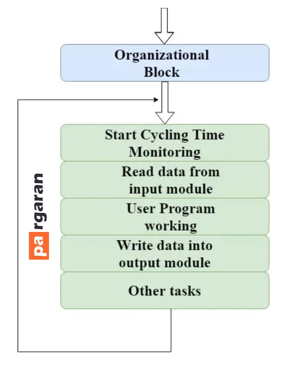
The operation of a programmable logic controller can easily be understood as a cyclical scanning method known as the scan cycle.
A PLC scan process includes the following steps:
- The operating system begins cycling and monitoring time.
- The CPU starts reading data from the input module and checks the status of all inputs.
- The CPU starts executing the user or application program written in relay logic or any other PLC programming language.
- Next, the CPU performs all internal diagnostics and communication tasks.
- Based on the program results, it writes data to the output module to update all outputs.
- This process continues as long as the PLC is in run mode.
Physical Structure of a PLC
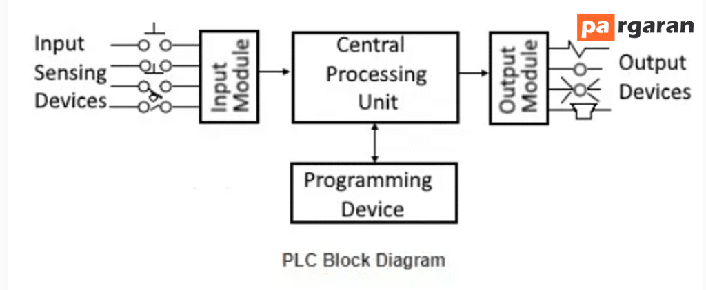
The structure of a PLC is somewhat similar to the architecture of a computer. Programmable logic controllers continually monitor the input device signals (such as accelerometers, weight scales, wiring signals, etc.) and produce the corresponding output depending on the production nature and industry.
A typical PLC block diagram consists of five sections:
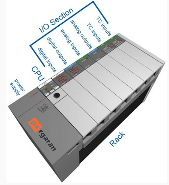
1- Rack or Chassis
2- Power Supply Module
3- Central Processing Unit (CPU)
4- Input & Output Module
5- Communication Interface Module
Rack or Chassis
In all PLC systems, the rack or chassis forms the most crucial module and acts as the backbone of the system. PLCs are available in various shapes and sizes.
When more complex control systems are involved, larger PLC racks are required. A small-sized PLC is equipped with a fixed I/O pin configuration.
Therefore, they proceed to the modular type rack PLC that accommodates various input/output modules with sliding and fitting concepts. All input/output modules will be housed within this rack/chassis.
Power Supply Module
This module is used to supply the power required for the entire PLC system. It converts the available AC power into DC power required by the CPU and I/O modules.
PLCs typically operate on a 24V DC power supply. A few PLCs use isolated power supplies.
CPU Module and Memory
The CPU module includes the central processor, ROM, and RAM memory. The ROM contains an operating system, drivers, and applications. RAM is used to store programs and data.
The CPU is the brain of the PLC with an octal or hexadecimal microprocessor. As a microprocessor-based CPU, it replaces timers, relays, and counters.
Two types of processors in either bit-level or word-level processing can be integrated with the PLC. Bit processors are used for performing logical functions, while word processors are used for processing text, numerical data, control, and data logging.
The CPU reads input data from sensors, processes them, and finally sends commands to the controlling devices.
The DC power supply, as mentioned earlier, is required for voltage signals. The CPU also contains other electrical components for connecting cables used by other units.
Input and Output Module
Are you thinking about how to sense physical parameters such as temperature, pressure, flow, etc.?
The PLC has a dedicated module for the input and output interface called the input and output module.
Input devices can include start and stop buttons, switches, etc. It also helps…