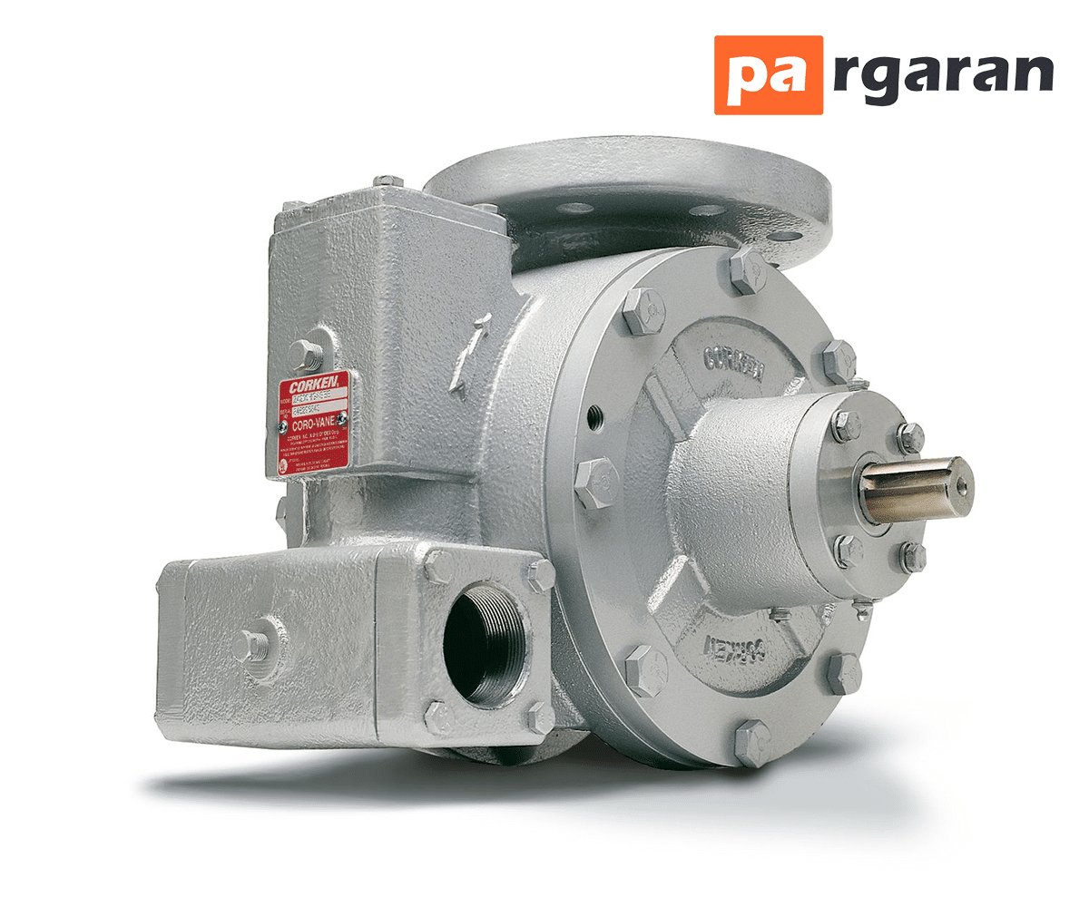
A vane pump is a positive displacement pump that provides a constant flow at various pressures. Its operation is carried out through a motor connected to a gearbox, as it typically has a maximum speed of 900 RPM.
Table of Contents:
- What is a Vane Pump?
- Working Principles and Operation of the Vane Pump:
- Components of This Pump
- Types of Vane Pumps
- Advantages, Disadvantages, and Applications of This Pump
The head of the pump consists of a slotted rotor containing vanes. The vanes create subdivided chambers in the pump head, dividing the pump head between the rotor and the outer casing, enabling the vane pump to self-prime as the chambers operate like valves.
The pump head is mostly circular but has a flat area due to the movement of the vanes in and out of the main rotor. The vanes press against the casing due to centrifugal force exerted while the pump is operating, pushing the vanes toward the body.
When the vanes reach the pump outlet, the chamber becomes smoother and tighter against the rotor, causing the vane to be pushed into the rotor, allowing fluid to exit from the pump outlet.

These pumps are most commonly used in air conditioning systems, power steering, and vehicles.
This positive displacement pump is used to convert high-pressure gas to low-pressure gas. Vane pumps are not suitable for highly viscous fluids. A vane pump can handle fluids with medium viscosity and is best suited for displacing low viscosity liquids such as alcohols, solvents, ammonia, and LPG.
These vane pumps are reversible, making them an excellent option for draining and emptying tanks.
Typically, vane pumps are equipped with a single mechanical seal, a double mechanical seal with barrier fluid, or gland packing. The vane pump head is made of stainless steel.
They are usually used for viscous fluids that act as lubricants such as oils, petroleum, diesel, animal/blood oils, and fuel oil. They can also control non-lubricating liquids like solvents due to the absence of metal-to-metal contact. Vane pumps self-compensate for wear, meaning they can maintain maximum performance without losing flow rate.
Operation of This Pump
- First, power is transmitted through an electric motor or engine to the shaft.
- The shaft is connected to the rotor, which rotates according to the shaft's rotation.
- This rotor has multiple vanes that rotate as the rotor spins.
- As the rotor spins, a vacuum is created inside the pump. For this reason, external water is drawn into the pump.
- With the entry of water into the rotor area, the rotor blades move the water outward due to centrifugal force.
- When the water strikes the vanes, these vanes rapidly convert the water's KE and send it towards the diffuser or spiral chamber area.
- The volute casing features a reducing area. Therefore, it converts the speed of water to pressure and increases pressure as needed.
- After pressurizing the water, it is discharged and reaches the desired area.
Components of the Vane Pump
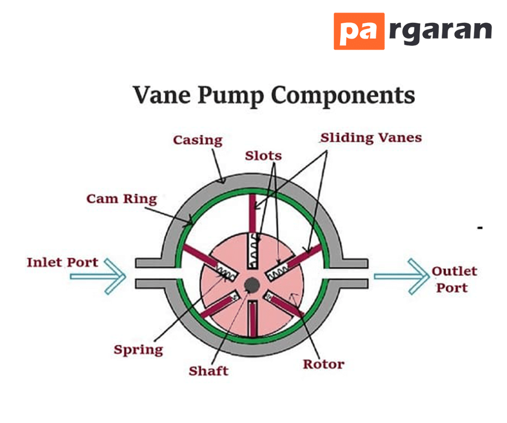
A vane pump consists of the following main components:
- Casing
- Inlet Port
- Outlet Port
- Vanes
- Rotor
- Shaft
Casing
This is the outer part of the rotary vane pump. It provides safety for all internal components of the pump, preventing damage to internal parts like the rotor, shaft, sliding vanes, etc., from external sources.
Inlet Port
This port is used to suck fluid into the pump. It acts as a one-way valve.
Outlet Port
After pressurizing the fluid, the pump discharges the fluid through the outlet port. It also acts as a one-way valve.
Shaft
The pump shaft connects to an electric motor. This motor supplies power to the shaft and rotates it. This shaft is primarily connected to the rotor.
Rotor
The most important part of the pump, playing a significant role in suction and pressure of the fluid. It connects to the shaft and rotates in accordance with the shaft's rotation. It has multiple vanes.
When the rotor spins, it creates a vacuum inside the pump as it sucks in the fluid.
Vanes
The vanes of the vane pump are installed on the rotor. The primary purpose of the vanes is to convert the kinetic energy of the fluid into its velocity. These vanes are rectangular in shape. The sliding vanes exist in the rotor grooves and move inside the grooves.
Types of Vane Pumps
- Unbalanced Vane Pump
- Balanced Vane Pump
- Variable Displacement Vane Pump
Unbalanced Vane Pump
This is the most common type of vane pump.
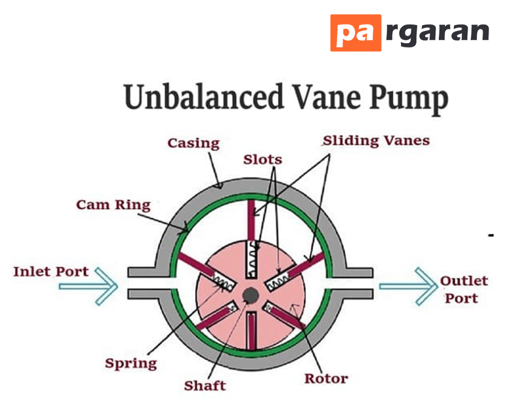
The pressure difference between the inlet and outlet valves causes a lateral thrust on the pump axis. This lateral thrust on the shaft shortens the bearing's life. This type of vane pump is known as an unbalanced vane pump due to the pressure difference between the inlet and outlet valves.
Conversely, a balanced vane pump does not have lateral thrust on the rotor shaft.
The unbalanced vane pump has a cylindrical rotor mounted on an offset circular casing. This means that the center of the cylindrical rotor does not align with the center of the casing. There is a specified distance between the center of the rotor and the center of the casing.
The rotor has a radial slot shaped in the drive shaft. The rotor moves in a ring, with each radial slot having a vane that can freely move inward and outward of the slot due to centrifugal force. The vanes are designed to contact the cam ring surface as the rotor rotates. There is no leakage between the casing and the tip of the vanes.
Balanced Vane Pump
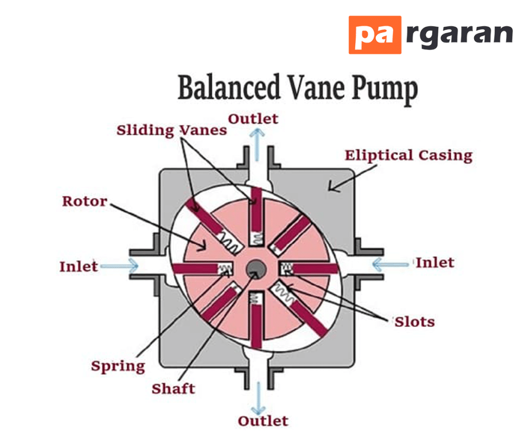
The balanced rotary vane pump has an oval casing. The oval body and rotor share the same center. There is no offset. These vane pumps are versatile in design and are commonly used in mobile and industrial applications.
No pressure differential is created between the inlet and outlet as this pump has two inlets and one outlet.
Two inlet ports are located directly opposite one another. Similarly, the outlet ports are also positioned on opposite sides.
This combination of inlet and outlet ports balances equal and opposite thrust forces, ensuring the rotor axis experiences no lateral thrust forces.
This pump provides better operational balance and longer lifespan.
The pump has a long useful life in many applications. In industrial applications, balanced vane pumps have a useful life of more than 24,000 hours.
The clearance between the two vanes decreases from the inlet side to the outlet side.
The pump suction fluid from the inlet port while discharging it from the outlet port.
The pressure applied to the rotor in the outlet area is significant. Forces in the two outlet areas are equal yet opposite. Therefore, there’s no net load on the shaft bearings.