How do sensors and actuators work in RTU and SCADA systems?
Controllers in RTUs
RTUs (Remote Terminal Units) are now made from small computers. Shortly after inception, control algorithms were programmed into RTUs. Flow totalizers, power factor calculators, and logic solvers soon followed.
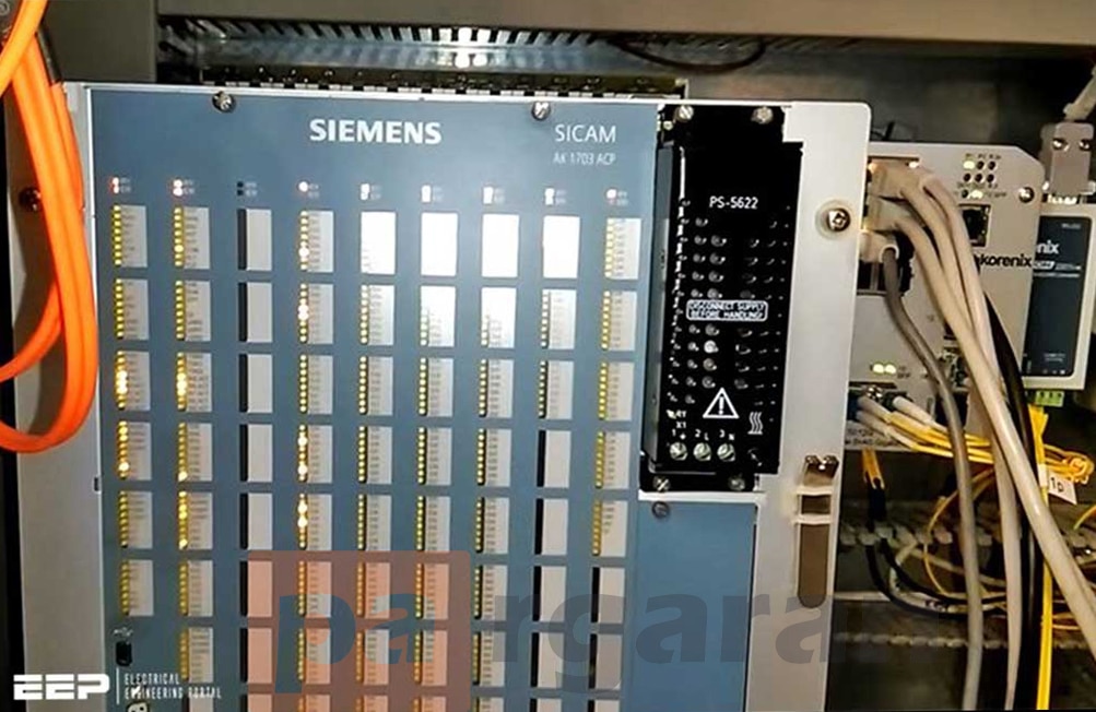
The RTU and SCADA System
Any function that can be described by a mathematical formula or algorithm can be processed by a computer in a relatively complex RTU. Signals are collected from field sensor devices. Algorithms are executed.
Control instructions are sent to valves or other control actuators. Some safety-related functions, such as fire or smoke detection and toxic gas concentration, are solved in dedicated hardware.
This is not because they have technically difficult algorithms, but because the regulatory organizations that approve them require them to be independent devices.
This unit focuses on some considerations to keep in mind when applying sensors and actuators. As used in SCADA, these devices may have little significant difference from tools used in any highly automated plant within a similar industry. However, they will differ from tools designed for direct reading by a human operator.
Purchasing and maintaining SCADA sensors and actuators can be expensive, a reality that must be considered when developing cost estimates for SCADA installation. Before the control algorithm is executed, the information received from the field sensor must be delivered as input to the RTU. Some communication must occur between the sensor and the RTU. Then, after solving the algorithms, some communication must occur between the RTU and the actuator. The RTU and SCADA System
Analog to Binary to Digital in RTU and SCADA Systems
All data transmitted between and RTUs is in binary data format. The binary data exists in this format that can be considered as the state of a switch to understand whether it is on or off.
Figure 1 shows the output of a limit switch that might be used to indicate the state of a valve. In Figure 1(a), the valve is open and the switch output is a steady +5 VDC. In Figure 1(b), the valve is closed and the switch output is a steady 0 VDC. The bottom of Figure 1 shows a switch output for a valve that is open, then closed, then open again, etc.

Figure 2
Figure1: Output from Limit Switch
Figure 2 illustrates how the output switch from a valve changes to a bit. The word bit is an abbreviation for binary digit. You see a single-bit register or flip-flop in Figure 2(a).
The switch output state of the valve feeds into the active input of the register, and the register outputs from the register. Figure 2(b) shows the timing logic. Just before time = 1, the valve opens, and the switch output state of the valve rises from 0 volts to +5 volts.
At time = 1, the clock pulse becomes positive (from 0 volts to +5 volts), which, along with the +5 volts at the active input of the register, causes the register to output a "1" (see the bottom line of Figure 2(b). The valve stays open for several clock cycles and then closes after time = 3.
When this happens, the active signal goes to 0 volts, but this does not change the output of the register. When the clock goes positive at time = 4, the register output changes to "0".
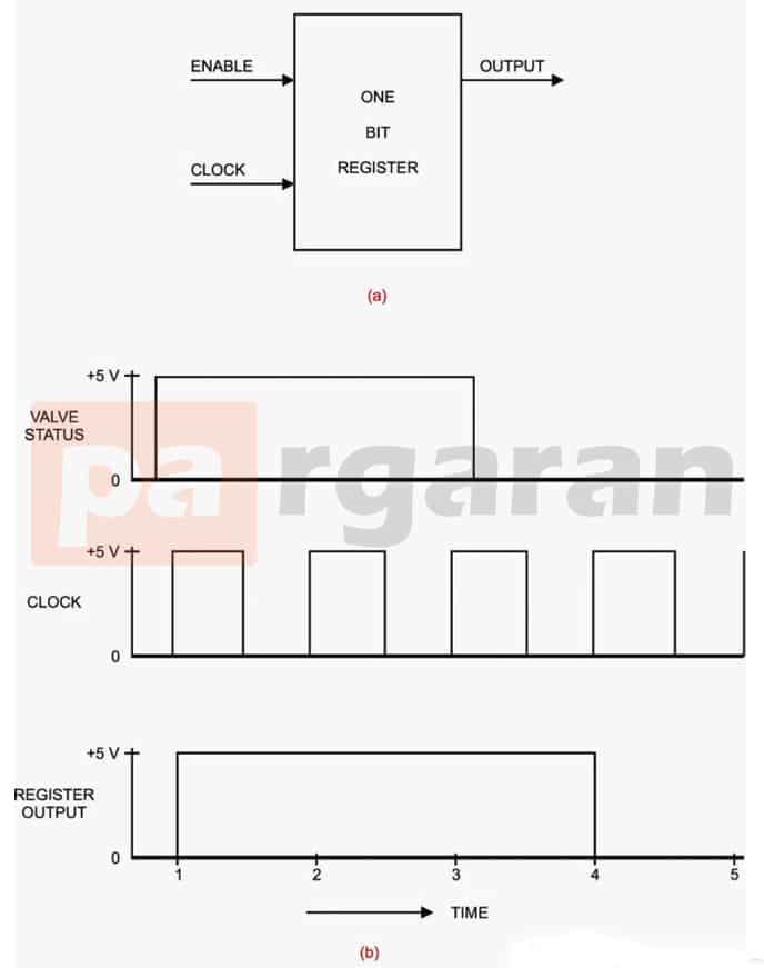
Figure2: Output Switch from Valve Changing to Bit
Figure 6-9 shows how an analog signal is generated to indicate the position of the valve. When the valve stem reaches its fully open position, the transmitter's output will be +5000 volts. When the valve is completely shut, the output will be 0.000 volts. As seen in Figure 2 above, the output is some value between 0 and 5 volts. Assume it is +3000 volts.
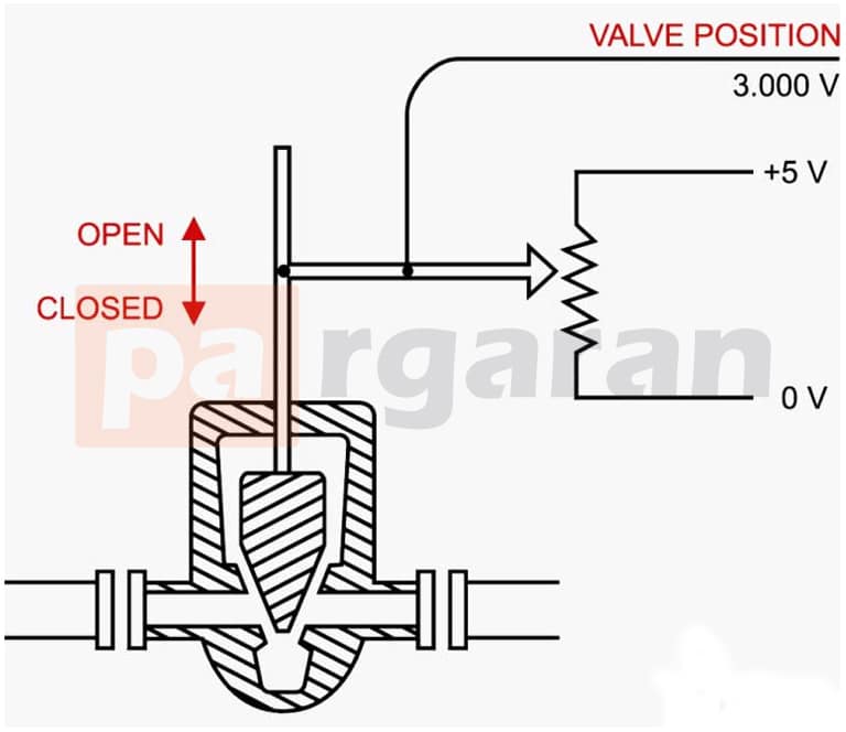
Figure3: Analog Signal Indicating Valve Position
How Does the RTU and SCADA System Work?
Starting from the top left of Figure 4, a signal of 3.000 volts is sent to the first stage of the ADC signal conversion. The converter tries to subtract 2.500 volts from it. Thus, the signal of 5 volts is given to the active input of the 2.500-volt bit (MSB) of the output register.
The next pulse in the MSB clock forces the register to have an output of 1. The remainder (3.000 - 2.500 = 0.500 volts) is fed into the second stage. The converter tries to subtract 1.250 volts from it. It cannot (since 0.500 is less than 1.250), therefore it outputs a 0-volt signal to the active input of the 1.250-volt output register. The remainder (still 0.500 volts) is fed into the third stage.
The converter tries to subtract 0.625 volts from it. It cannot (since 0.500 is less than 0.625), so it outputs a 0-volt signal to the active input of the 0.625-volt output register. The next clock pulse that registers the bit as "0" powers it.
The remainder (still 0.500 volts) is then fed into the fourth stage. The converter attempts to subtract 0.3125 volts from it. Thus, a +5 volt signal is output to the active LSB input of the output register. The next clock pulse that registers the bit as "1" powers it.
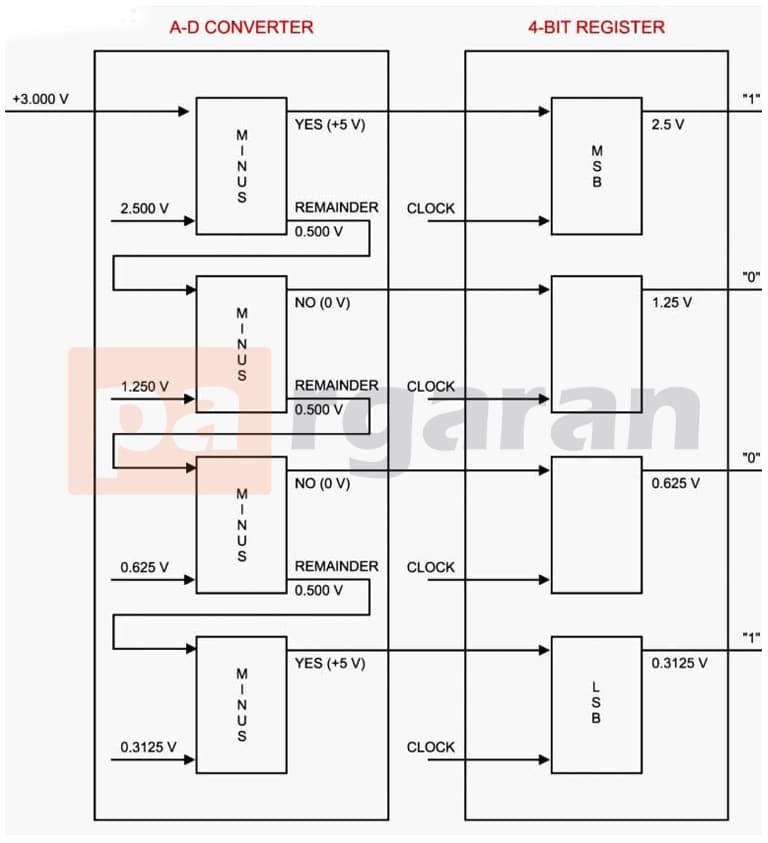
Figure 4- Analog to Digital Converter
The result is a four-bit binary character describing the value of 3.000 volts as follows: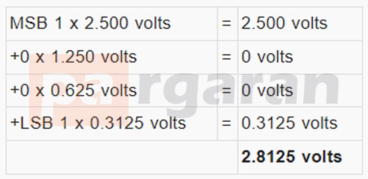 Since a four-bit register provides a precision of 1 in 24 or 1 in 16, we are thus allowed to represent the value to be 3.000 volts. In some applications, the signal shifts from positive to negative. For this reason, an additional bit must be used as extra bits provide increased precision.
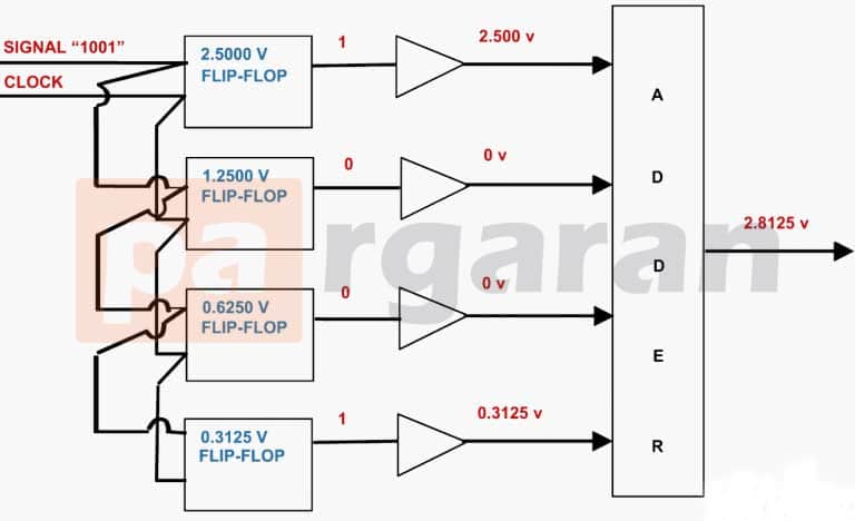
Figure 5- Digital to Analog Converter (DAC)
Digital to Analog Converters (DAC) are devices that take a digital signal and convert it to an analog value. Figure 5 shows how this is done. Using the digital value provided by the ADC as seen in Figure 4, we place the highest bit at the active flip-flop activation port.
When the clock pulse causes any of these flip-flops to activate, 5 volts at the output of each flip-flop corresponds to a 1 appearing at the input. 0 volts at the output of each flip-flop corresponds to 0 volts appearing at the input.
The voltage switches each have two inputs. One allows voltage to pass from the switch, while the other blocks this path. The other input is the switching signal (the status change signal). If it is 5 volts, the precise voltage passes through. If it is 0 volts, the precise voltage does not pass through.
The second voltage is exactly half of the first voltage, and so on. The summing block on the right adds each of its inputs and then outputs the result that is the sum of the inputs. In this case, the output would add 2.500 volts plus 0.3125 volts for an output of 2.8125 volts.
...