The cost of fuel and fuel-saving features of continuously variable transmissions (CVT) are driving the capability of CVT into larger and larger off-road vehicles. The architecture of hydro-mechanical transmission allows for smaller hydraulic components to provide cost-effective CVT performance for larger machines. As a result, the number of hydro-mechanical transmissions in the market is on the rise.

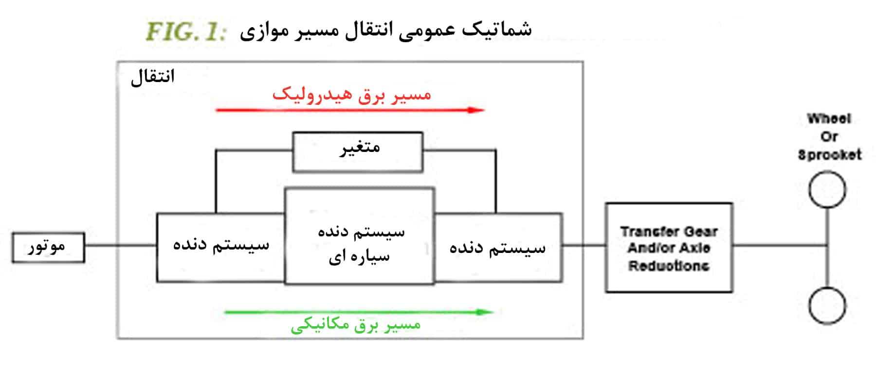
A conceptual schematic of hydro-mechanical transmission with two simple parallel power paths (Figure 1)
The hydraulic path consists of a pump and motor, which are referred to here as "variable." The mechanical path typically features a shaft with perhaps one or two gears. These paths are interconnected with conventional mechanical transmission components such as gears, shafts, clutches, and at least one planet.
There are a vast number of connection possibilities. In a specific design, the details of these connections constitute a substantial portion of the intellectual property and suitability for the intended machine application.
Hydro-mechanical transmissions have long been available in agricultural tractors. They are either standard or offered as an option (Figure 2).
Generally, hydro-mechanical transmission has not been available in earth-moving equipment until now. It is believed that the wheel loader segment benefits the most from CVT, and this is where the latest offerings can be found. Examples that are available are shown in Figure 3 and are now either available or will be offered soon.
Three things distinguish designs in hydro-mechanical transmission:
- First, the construction of the variator and its location, for example, variable displacement pump, bent shaft motor with fixed displacement, which is mounted inside.
- Second, the type of coupling. Common terms include: input coupled, output coupled, and compound split. While the specifics of this nomenclature exceed the scope of this paper, it generally explains whether the input or output shaft of the transmission is directly connected through the gear ratio to one of the variable shafts or not. In the case of compound split, none of the variable shafts are directly connected.
- Third, the number of ranges or modes. This is the number of different mechanical connections that are created between mechanical and hydraulic paths by engaging and disengaging any clutches in the gear systems. Note that the type of coupling is not necessarily the same for each range or mode.

(Figure 2): Hydro-mechanical transmissions in agricultural tractors
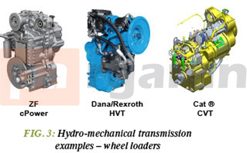
Figure 3: Hydro-mechanical transmission in earth-moving equipment
Consider the engine fuel map in Figure 4. The vertical axis represents engine power, and the horizontal axis represents engine speed. The peak of each contour indicates the maximum power of the engine for that fuel rate. The location of these peaks defines the best engine speed for minimum fuel consumption.
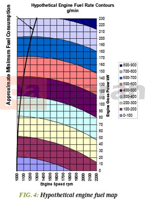
Figure 4: Engine fuel map
Consider the drivetrain you saw in Figure 5. The chart at the bottom of the figure shows that for a given ground speed, only one or two engine speeds may be possible. It is unlikely that one of these speeds will fall on the minimum fuel consumption line of Figure 4.
Additionally, forecasted load changes, especially if there are issues in changing ratios, may lead the operator to select a higher engine speed (and more fuel consumption) and/or a lower ground speed (slower cycle time).
Consider the powertrain system in Figure 6. The chart at the bottom of the figure shows that for a specific ground speed, nearly any engine speed may be possible and thus could match the minimum engine speed fuel consumption seen in Figure 4. The engine speed lines from the graph in Figure 5 are included for reference. As modern hydro-mechanical CVTs have excellent ratio changes, there are few issues related to load changes, such as discrete step transmissions.
While the information in this article may not provide you with the design of a hydro-mechanical transmission, it enables you to more easily recognize them and their potential advantages.
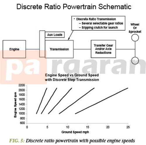
Figure 5: Engine speed lines from the graph
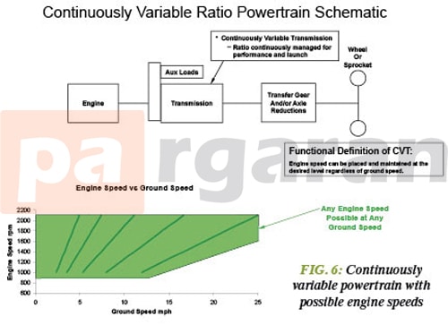
Figure 6: Power train system
I hope you enjoyed reading the article (What Distinguishes Designs in Hydro-Mechanical Transmission?).
For any questions or suggestions, please contact the Pargaran team.
For more information, click here.