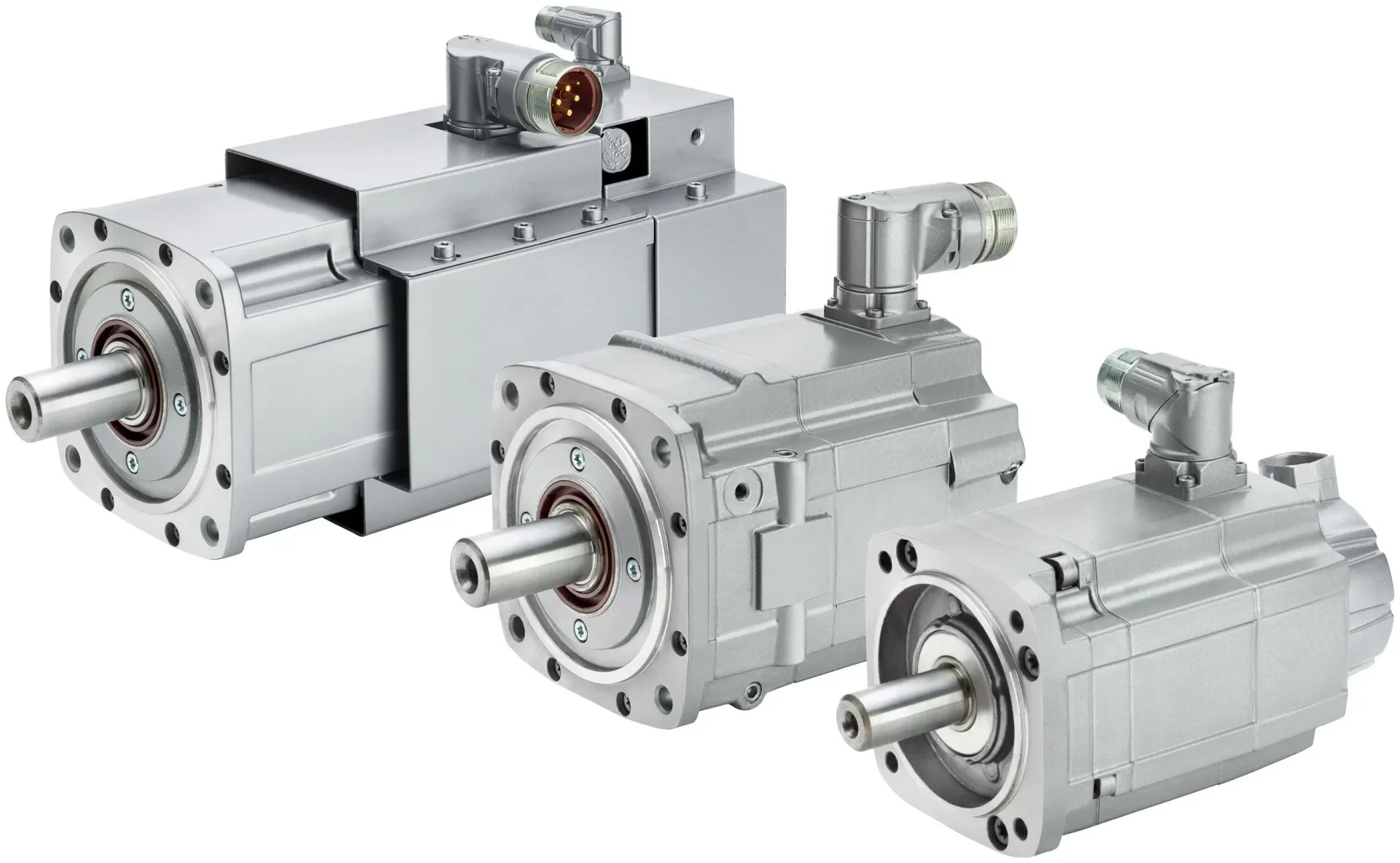
Electric Actuator, a modern type of actuators equipped with electric motors, can be used for manual and remote operation of industrial valves. They are also known as electric valves, electric drives, electric actuators, and workshop valve automation. They are used to control flow rates and monitor the operation of valves in various systems and industries.
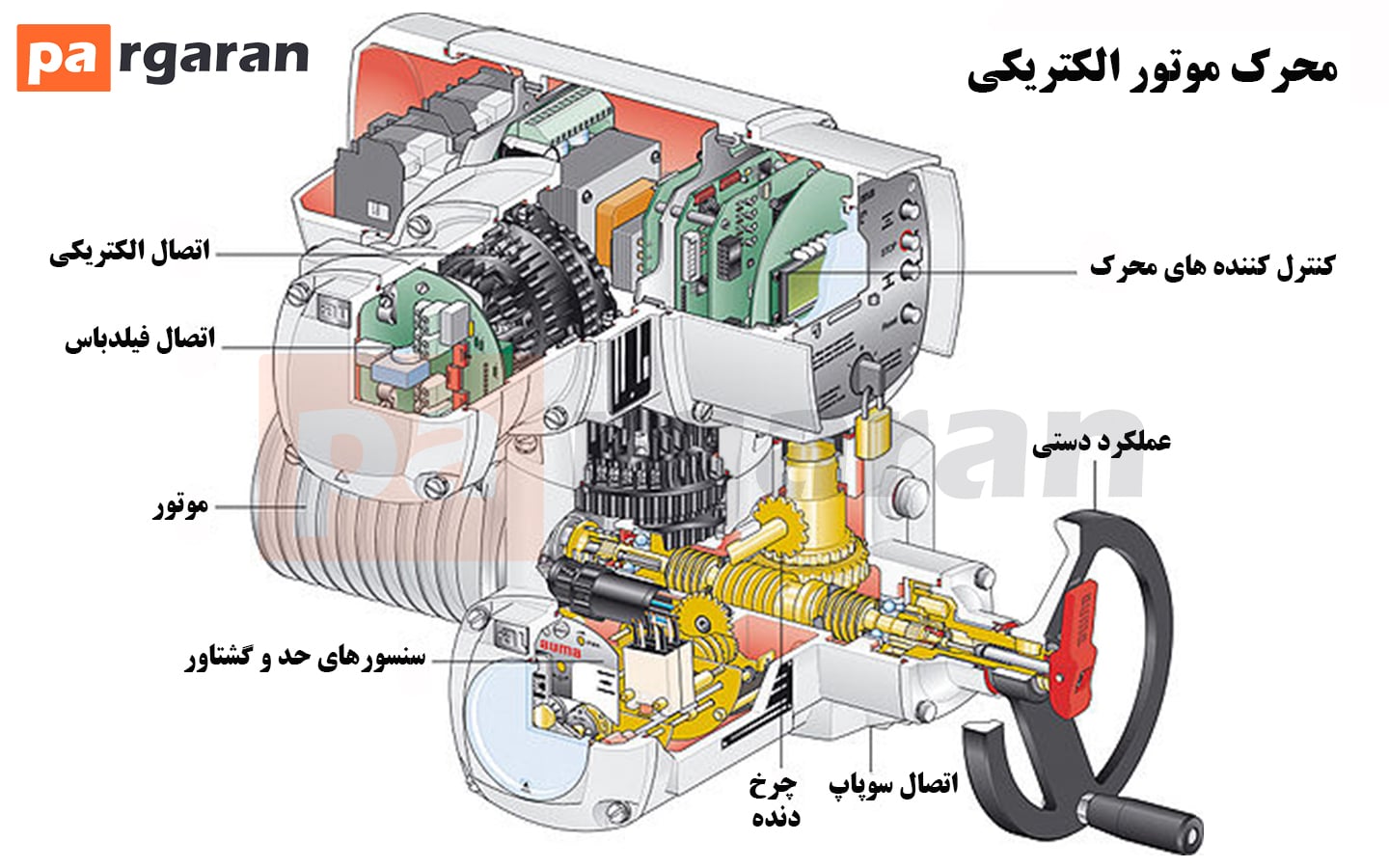
These types of actuators consist of an electric motor, control system, gearbox, and limit switch.
In electric actuators, the speed of the electric motor is reduced using a gearbox, allowing it to easily reach the desired rotational speed. The gearbox makes the actuator precise and stable. In systems requiring precise control, control systems in actuators are used as they simplify the control process significantly.
Due to their power source and lack of leakage or pollution, these actuators are considered clean equipment. They are relatively more expensive than other actuators, but due to having fewer moving parts, they incur low maintenance costs and have higher energy efficiency.
These types of actuators are manufactured according to IP67 and IP68 standards and ICE Europe, and they can be reliably used on all valves, including multi-turn rotary valves such as:
- Gate valves
- Globe valves
- Quarter-turn valves such as ball valves and butterfly valves
- Needle valves
- Plug valves
- Industrial gates
- Dampers
Full-turn or multi-turn actuators are suitable for globe, gate, slice, penstock valves, dampers, etc., capable of producing up to 100,000 Newton meters of torque with their gearbox.

Advantages of Electric Actuators
- Adjustable speed
- Accuracy and flexibility
- Lightweight and compact
- Low operational costs
- Uniform information output
- Remote controllable
- High durability and longevity
These strengths ultimately lead to use in industries like robotics, electronics, electronic assembly, tools, and many other industrial sectors.
Disadvantages of Electric Actuators
- Higher cost compared to pneumatic actuators.
- In case of power outage, they remain in the same position, and a safe position for failure cannot be easily obtained unless there is a suitable stored electrical energy source.
- Electric actuators should operate in sufficiently safe environments and are not generally recommended for flammable environments.
- Care should be taken not to unnecessarily use stronger motors.
Components of Electric Actuators
-
Components of Electric Actuator Motor
The electric motor creates a rotary motion through the rotation of the rotor or spindle. The spindle is attached to the shaft via a screw and rotates it. The motor is controlled by an electric drive. Proper power supply and related wiring for the equipment are essential for the operation of electric actuators, as well as wiring for power and control signals between the motor and drive, which we describe in the diagram below.

Motor:
Typically, three-phase and single-phase AC motors are used to generate the necessary torque for the actuator. DC motors are also used depending on the application requirements. It is expected that actuators operate under severe environmental conditions, but they are generally not used for continuous work as the motor's heat generation can be excessive.
Torque Sensor:
These sensors are typically used to determine the disk's position and stop the motor upon reaching the desired position.
Gear:
Worm gears are commonly used to reduce the high output speed of the electric motor. The primary application of the gearing is to reduce the rotational speed of the shaft connected to the motor and convert it into the necessary torque to turn the disk. Therefore, the gearbox self-locks, meaning it prevents the valve's position from accidental and unwanted shifts while acting on the valve-closing element.
Connection:
The actuator connects to the valve in two parts. First, its flange connects the actuator to the valve body. The higher the torque required to open and close the valve, the stronger the flange required. The second part connects the motor shaft to the valve stem.
Manual Valve Actuator:
When the motor's operation is disrupted for any reason, manual opening or closing of the valve may be necessary; therefore, many actuators are equipped with a manual lever or handwheel to manually adjust the valve's position.
Electronic torque limit switches do not operate during manual operation. Mechanical torque limiters are typically employed to prevent torque overload during manual operation.

Components of Linear Electric Actuators
Electric Motor
Control System
Gearbox
Limit Switch
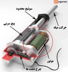
Technical Specifications of Electric Actuators
These actuators are selected based on the produced torque and input voltage. The selection of electric actuator power depends on the size of the valve it is installed on and the fluid pressure inside the line.
Electric actuators can control the valve in either an open-closed manner or proportional control (with an analog signal input of 4 to 20 mA or 0 to 10 volts). These control valves are also available as motorized two-way and three-way valves.
Classification of Electric Actuators in the HVAC Industry
HVAC stands for Heating, Ventilating, and Air Conditioning, and encompasses technologies related to creating comfort in indoor building environments. The design of HVAC systems is one of the main subfields of mechanical engineering, based on the principles of thermodynamics, fluid mechanics, and heat transfer.
Two-way and three-way motorized valves are widely used in industrial and HVAC installations. These valves are available in on/off, incremental, and floating types. An important point about actuators commonly used in the HVAC industry is that often only actuators from a specific brand can be used on valves of the same brand; for example, a Honeywell actuator cannot be installed on a Danfoss valve.

Three Types of Electric Actuators in the HVAC Industry
-
On/Off Actuators
Operation...