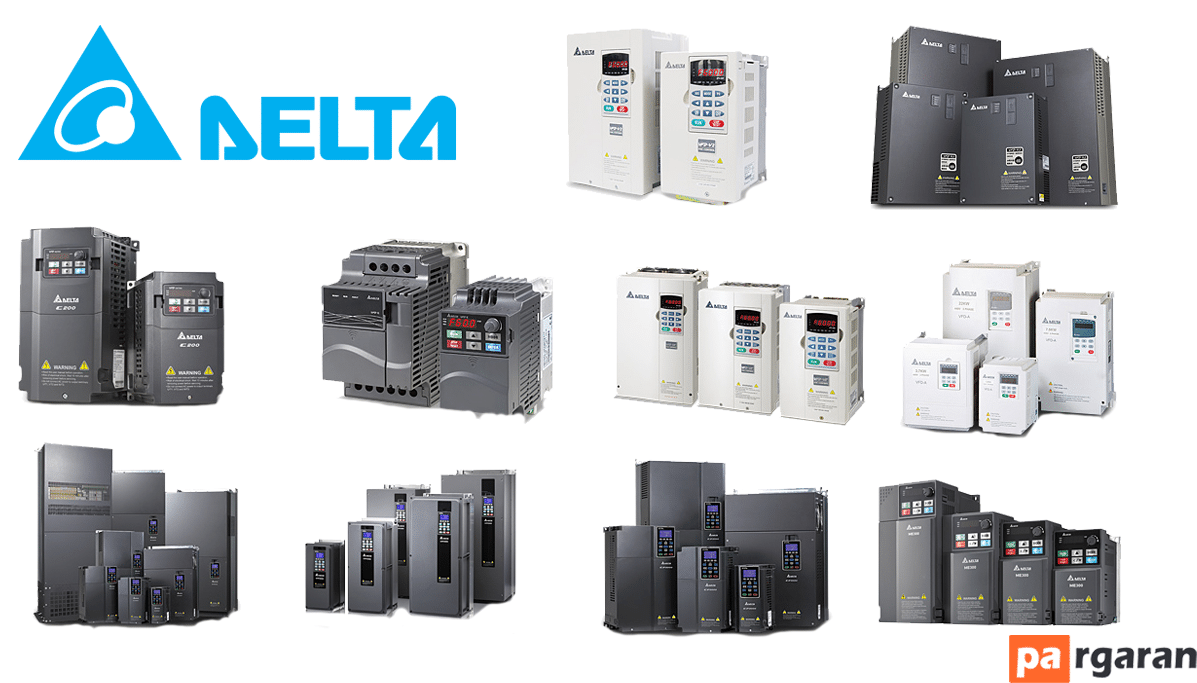
The Delta brand inverter is widely used in industry and is one of the most common automation equipment. In this comprehensive article, we aim to introduce the different types of Delta drives and how to use them.
What is a Delta Inverter (Variable Frequency Drive)?
A Variable Frequency Drive (VFD) is a type of motor controller that drives an electric motor by varying the frequency and voltage supplied to the motor. Other names for VFD include: variable speed drive, adjustable speed drive, adjustable frequency drive, AC drive, microdrive, and inverter.
Frequency (or Hertz) is directly related to the speed of the motor (RPM). In other words, the faster the frequency, the faster the RPM goes. If an application does not require the electric motor to operate at full speed, the VFD can be used to reduce frequency and voltage to meet the electric motor's load requirements.
As the speed requirements of the motor change, the VFD can simply increase or decrease the speed of the motor to meet the necessary speed.
How Does a Variable Frequency Drive Work?
The first stage of an AC Variable Frequency Drive or VFD is the rectifier. The rectifier comprises six diodes, similar to check valves used in piping systems. They allow current to flow in only one direction.
For example, whenever phase A voltage (analogous to pressure in piping systems) is more positive than phase B or C voltage, that diode opens, allowing current to pass. When phase B becomes more positive than phase A, the phase B diode opens, and the phase A diode closes.
The same applies to the three diodes on the negative bus. Thus, by opening and closing each diode, we receive six "pulses" of current. This is called the "six-pulse VFD", which is the standard configuration for current variable frequency drives.
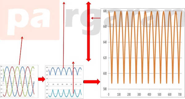
We can mitigate AC ripple on the DC bus by adding a capacitor. A capacitor functions similarly to a tank or battery in a piping system. This capacitor absorbs AC ripples and provides a smooth DC voltage.
The AC ripple on the DC bus is typically less than 3 volts. Therefore, the voltage on the DC bus becomes "approximately" 650VDC. The actual voltage depends on the AC line voltage feeding the drive, the voltage imbalance in the power system, the motor load, the impedance of the power system, and any reactors or harmonic filters on the drive.
The diode bridge rectifier that converts AC to DC is sometimes simply referred to as the rectifier. A device that converts DC back to AC is also a rectifier; however, to distinguish it from the diode rectifier, it is commonly called an "inverter." It has become common in the industry to refer to any DC-to-AC converter as an inverter.
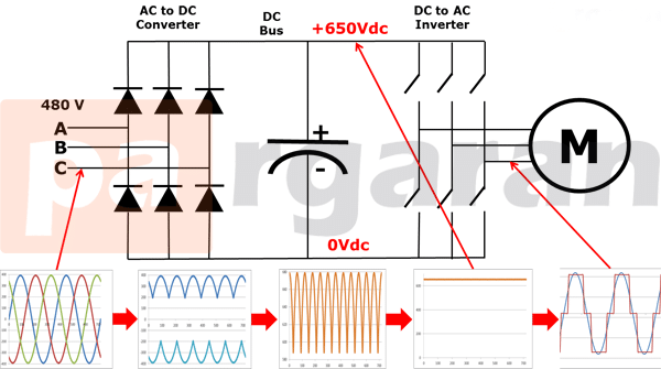
Note that in a real VFD, the switches depicted are actually transistors.
When we close one of the upper inverter switches, that motor phase connects to the positive DC bus, making its voltage positive. When we close one of the lower rectifier switches, that phase connects to the negative DC bus, making it negative.
Thus, we can make any phase on the motor positive or negative at will, effectively generating any frequency we desire. Hence, we can make any phase positive, negative, or zero.
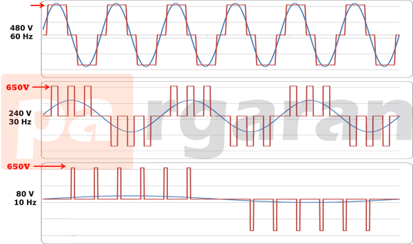
The blue sine wave is shown for comparison purposes only. The drive does not generate this sine wave.
Note that the VFD output is a "square wave" form. VFDs do not produce sine wave output. This square waveform is not suitable for a public distribution system, but it is perfectly suitable for a motor.
If we want to reduce the motor frequency to 30 Hertz, we simply slow down the switching of the inverter output transistors. However, if we reduce the frequency to 30 Hertz, we must also reduce the voltage to 240 volts to maintain the V/Hz ratio (for more information on this, refer to the VFD motor theory presentation). If the only voltage we have is 650VDC, how do we intend to reduce the voltage?
This is known as Pulse Width Modulation or PWM. Imagine if we could control the pressure in a water line by rapidly turning a valve on and off. While this might not be practical for piping systems, it works very well for VFDs.
Note that in the first half cycle, the voltage is on half the time and off half the time. Therefore, the average voltage is half of 480 volts or 240 volts. By pulsing the output, we can achieve any average voltage at the VFD output.
Why Should I Use a VFD?
1 - Energy Consumption and Cost Reduction
If you have an application that does not require it to run at full speed, you can reduce energy costs by controlling the motor with a variable frequency drive, which is one of the advantages of variable frequency drives. VFDs allow you to match the speed of the motor-driven equipment to the required load.
There is no other method for controlling an AC electric motor that allows you to do this. Electric motor systems account for over 65 percent of the electricity consumed in today’s industry.
Optimizing motor control systems by installing or upgrading to VFDs can reduce energy consumption in your facilities by up to 70 percent. Additionally, using VFDs improves product quality and reduces production costs. By combining energy efficiency tax incentives and utility rebates, the ROI for VFD installations can be as quick as 6 months.
2 - Increased Production Through More Accurate Process Control
By operating your motors at the most efficient speed for your application, fewer mistakes occur, resulting in increased production levels which bring more revenue to your company. In conveyors and belts, you eliminate jolts during startup to allow smoother transitions.
3 - Increased Equipment Lifespan and Reduced Maintenance
When your equipment is controlled by a VFD and ensures optimal motor operating speed, they will last longer and have less downtime due to repairs.
Because of optimal control of the VFD motor's voltage and frequency, VFD offers better protection for your motor against issues such as thermal overloads, phase protection, under-voltage, over-voltage, etc. When starting a load with a VFD, the motor or load isn't subjected to an "instantaneous shock" across the line but can start gradually.
This eliminates wear on belts, gears, and bearings. It is also a great way to reduce or eliminate water hammer because we can have acceleration and deceleration cycles.
Delta Inverter Input and Output Terminals
They have two main sections.
- Power terminals
- Control terminals
Power terminals have high voltage and current and provide power from the grid to the drive...